This product was added to our catalog on Saturday 22 December, 2012.
Heat Exchanger Hayward FD400 Heater FDXLHXA1400
[FDXLHXA1400]
Price:
Heat Exchanger Assembly for Hayward FD400 Heater FDXLHXA1400
Heat Exchanger Replacement Procedure
Heat Exchanger Service Parts Kits
for Universal H-Series (Forced-Draft) Heaters
IMPORTANT NOTES:
- This kit is intended to be used only with Hayward Universal H-Series (forced-draft) gas heater models.
These heaters may be identiied by inspection of the heater
rating plate (there should be an "FD" in the model number),
or by visual inspection of the heater in comparison to the
diagrams in these instructions.
- This instruction sheet is intended for the following heater
service parts kits:
|
P/N |
Description |
| FDXLHXA1250 |
Heat Exchanger Assembly, H250FD |
| FDXLHXA1350 |
Heat Exchanger Assembly, H350FD |
| FDXLHXA1400 |
Heat Exchanger Assembly, H400FD |
REPLACEMENT PROCEDURE
- Tum pump, main as valve, and heater power off.
- Remove drain plug and drain water out of heat
exchanger.
- If necessary, disconnect header union fittings from
pool/spa piping.
- Pull temperature limit switch wires through the
grommet on the heater side panel. and disconnect limit
switch wires from heater wire hamess.
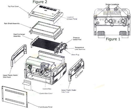
- Remove screws and remove both of the upper plastic heater side panels (see Figure 1 for screw locations,
and Figure 2 for part locationhdentification).
- Disconnect the 2 wires from the pressure switch. which
is located on the inletloutlet header.
- Remove countersunk screws on heater top and
remove louvered exhaust panel on heater top (see
Figure 2).
- Remove the heater top tlue cover by removing 3
screws on each side of the heater (see Figure 2).
- Remove screws and remove rain shield assembly (see
Figure 2). Note that there are screws which hold the
rain shield assembly to the heat exchanger tube
sheets, which also must be removed.
- Remove the front access panel and the control box
cover (see Figure 2).
- Disconnect the temperature sensor plug from the
circuit board located inside the control box.
- Pull the temperature sensor wires out of the control
box and through the hole in the heater cabinet.
- Carefully lift the heat exchanger up and out of the
heater cabinet.
- Before installing the new heat exchanger assembly,
install the new adhesive-backed gaskets (included in
this kit) onto both ,of the new heat exchanger tube
sheets.
- Install the new heat exchanger assembly. Ensure the
heat exchanger is properly oriented with the arrows on
the tube sheet decal pointing up.
CAUTION: Do not install heat exchanger upside
down. Heat exchanger is labeled to indicate the
proper orientation. The heat exchanger will be
damaged if installed incorrectly.
- Remove the pressure switch from the old heat
exchanger assembly and install on the new heat
exchanger assembly. Apply pipe thread sealant to the
pressure switch threads before assembly.
- Reverse the above steps to reassemble the heater.
- Activate water pump and check the system for leaks.